2D modelling vs. 3D modelling for as-built capture
Time is changing. While in many areas people still work in 2D, others have recognised and implemented the advantages of 3D modelling long ago. Especially in the fields of industry and automotive engineering, 3D modelling has become firmly established and is constantly developing.
In architecture, we are experiencing a rather timid change. The 2D analyses of floor plans, sections and views are a familiar and firmly rooted basis for creative planning and conversion work. Ideas are developed on sketch paper, materials are assigned, rooms are furnished – and then digitally implemented.
We are often asked where the real added value of a 3D model is? Where exactly are the advantages or disadvantages of 2D or 3D modelling and which variant should you use in your next project?
2D modelling
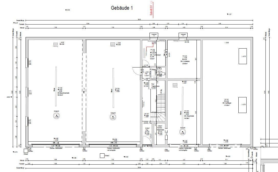
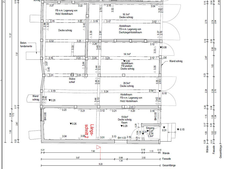
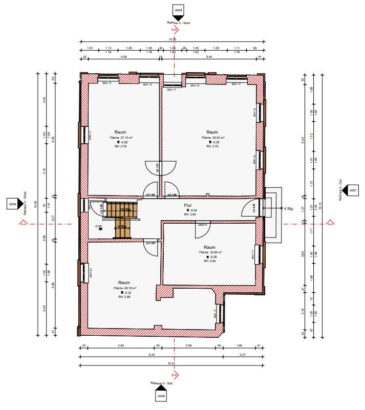
When analysing in 2D, floor plans, detailed plans, facade views and sectional views are usually generated. The number and location are defined in advance. 2D plans have existed for many years; the plans are standardized, understandable for everyone and correspond to predefined accuracy guidelines. The data is compact and has a small file size. The exchange is uncomplicated and the data can be read by any software.
3D modelling
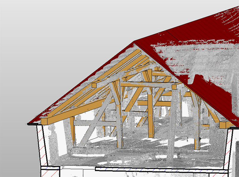
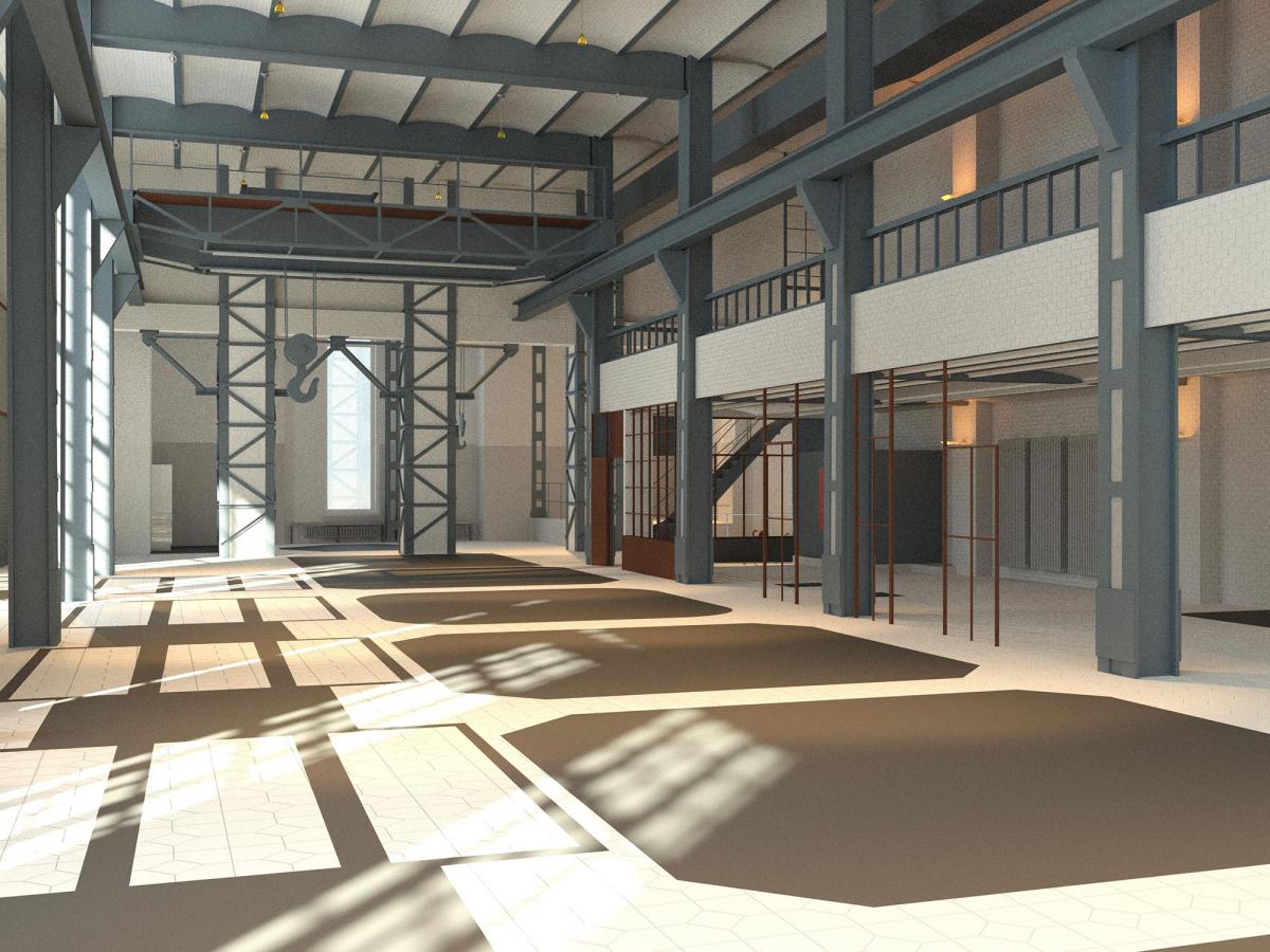
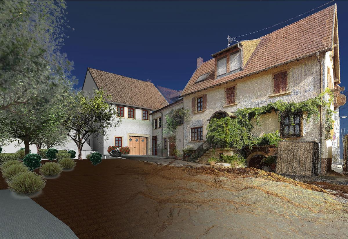
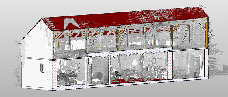
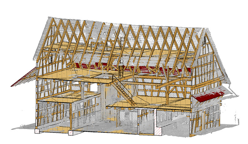
3D modelling is the modern form of as-built documentation. The entire elements "building", the technical installations and, if required, the furniture are captured "as-built" and represented in the 3D model in XYZ dimensions. We distinguish between modelling as a pure wireframe model and modelling as a parametric 3D model. Software solutions such as Autodesk Revit or ArchiCAD are used for this.
The wireframe model is often sufficient for conversion planning and collision detection, but does not provide any further information about the object beyond the pure geometry data.
Parametric models have component libraries, fixed or freely defined parameters in the component types (walls, ceilings, stairs, windows, doors) and can be placed with dependencies to each other. A lot of information, which was previously kept in complex additional lists, can be integrated directly into the model or linked to the model.
In 3D modelling, customers can easily visualise the objects; model derivations for detailed views or complicated building areas can be quickly created at any position. The data exchange takes place via the IFC interface (Industry Foundation Classes) and can be referenced and imported by many 3D software solutions.
2D modelling vs. 3D modelling (parametric) in the as-built survey
For both analysis methods almost identical basics are used. Manual measurements, surveys, scan data (point clouds) from laser scanners and UAV, orthophotos, photos, historical documents and building descriptions are used. The main differences are in the further processing and are described and explained in the following chart.
| 2D modelling | 3D modelling | |
|---|---|---|
| Hardware requirements | 8 – 16 GB RAM Microsoft Windows 7 – 10 Hard disk space: 6 GB Processor: 2 GHz | 16 – 64 GB RAM Microsoft Windows 10 Hard disk space: 30 GB Processor: more than 3 GHz |
| Software solutions | e. g. AutoCAD, GEOgraf, Card_1, MicroStation, BricsCAD | e. g. Autodesk Revit, ArchiCAD, MicroStation, AutoCAD Architecture, Allplan |
| Requirements to the modeller | A good educational background and technical knowledge are excellent prerequisites for the creation of 2D planning data. Working with the various software solutions can usually be learned quickly and does not require a long training period. | The 3D software solutions usually differ greatly from each other. Without appropriate training in the software, getting started is often difficult and time-consuming. The modeler himself should be able to generalise intelligently and distinguish important details from unimportant ones, so that the models do not unnecessarily consume data space. Experience, a good education and a good spatial imagination play an important role here. |
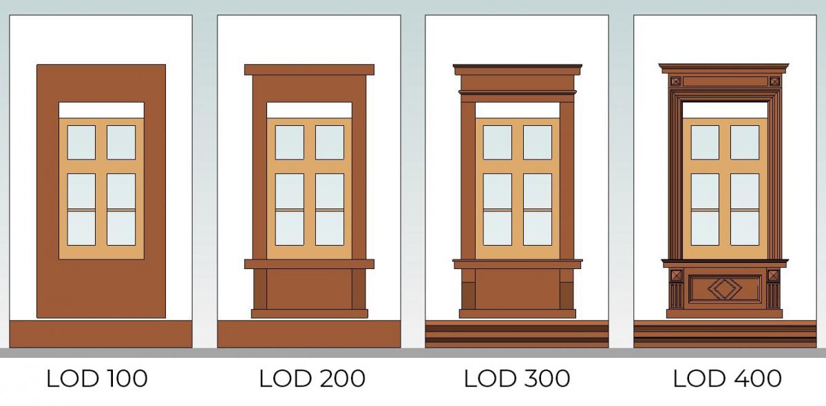
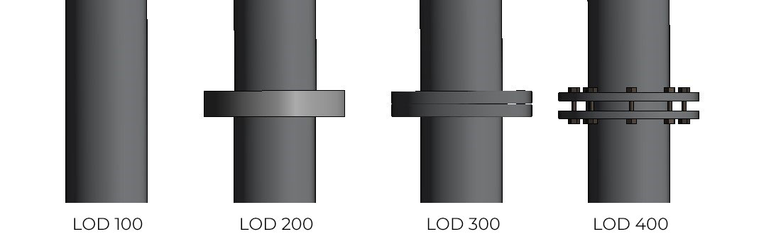
| Accuracies and standards | Defined by various accuracy classes and levels and by DIN specifications and standards. | Defined via BIM standards and the Level of Detail (LOD) |
| 2D modelling | 3D modelling | |
|---|---|---|
| Measurement true to deformation | Given the position of the building section, it is very easy to create the plans according to the deformation, e.g. to draw an inclined wall at an angle. Unfortunately this representation does not reflect the whole building like "as-built", but always only the respective section. | Model remains model! A complete deformation-compliant modelling is possible but very complex, expensive and difficult to export and process. An implementation of standards and an agreement with the customer before project start is very reasonable and recommendable. |
| 2D modelling | 3D modelling | |
|---|---|---|
| Analysis time | The time always depends on the scope of the analysis. Experienced modellers are faster than beginners. Example: Single family house with basement, ground floor, first floor, roof, 4 facades and 2 vertical sections approx. 40 hours | Professional and experienced 3D modellers achieve an almost identical analysis time as 2D modellers. For large projects the analysis time even changes in favour of 3D modelling. Example: Single family house with basement, ground floor, first floor, roof, 4 facades and 2 vertical sections approx. 40 hours |
| Plan derivations | Each plan (floor plan, section, view) is drawn separately; the position and perspective of the plans should be defined in advance. Changes and additions involve a lot of rework. Depending on the level of accuracy, the plans are very detailed, since as much information about the building as possible must be presented in the plan. | Plan derivations can be quickly generated at any position in the model. An exact agreement, e.g. regarding the position and perspective of vertical sections, is still possible until the end of the project and can be changed at any time. The information content of the plan derivations is not comparable with the plans of the 2D analysis, since all the information is contained in the model and does not have to be defined in the plan. Many customers are initially disappointed with the relatively simple plans, but are ultimately convinced and enthusiastic about the wealth of information and potential in the model. |
| 2D modelling | 3D modelling | |
|---|---|---|
| Planning basis | Suitable for further planning in 2D. | Suitable for further planning in 3D. |
| BIM capability | Less suitable for further processing in a BIM software | Perfectly suited for further processing in a BIM software |
| Additional information | Additional information (e.g. materials, state of construction) on the object must be provided in external documents and/or supplemented in the plan itself via annotations and special geometry types (e.g. hatching, symbols, colour and line types). | All additional information can be saved, accessed, output and listed directly on the object. |
| Output of component lists (e.g. window and door lists) | The component lists are usually created manually and handed over in the form of documents, such as Excel or Word files. In the process, transposed numbers, duplications and other errors often creep in. | In a parametric 3D modelling software, the component lists can be generated automatically. Sources of error by the processor himself are minimized. |
| Part libraries, blocks | Libraries can also be created and used in 2D modelling; variable blocks (e.g. for windows and doors), cells or signatures are used and simplify the work. However, these blocks are without the third dimension and are usually broken down into their original geometry for data exchange. | Many parametric 3D software solutions offer already existing component libraries, which facilitate the start into 3D modelling. However, in the course of modelling, you will soon realise that these specifications are usually not sufficient to handle an entire project. The creation of new user-defined library elements (e.g. Autodesk Revit families) requires some experience and usually does not work in practice without training. |
| Cooperation between different trades | If all trades that come together (e.g. heating, plumbing, electrical) can dispense with the third dimension, cooperation is easily possible due to the simple exchange of data. | If the as-built model is available in 3D, all cooperating trades should also produce their plans in 3D. A combination of 2D and 3D data makes little sense for the planning and identification of narrow, complicated areas (e.g. in installation rooms). |
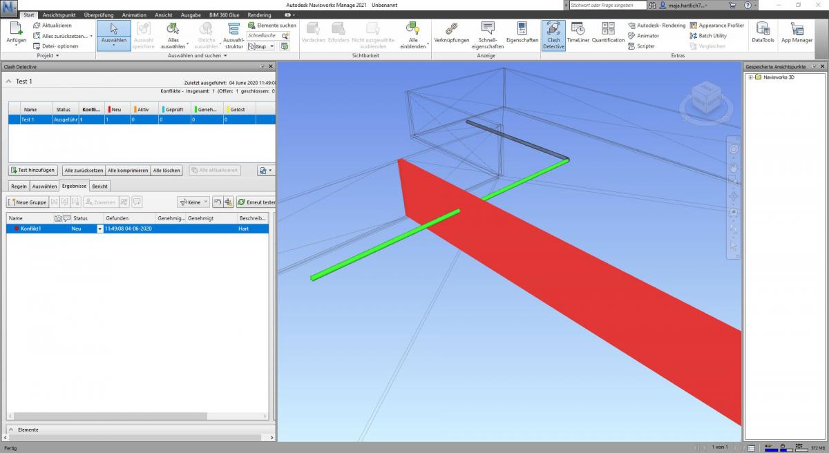
| Collision analysis | A complete collision check is almost impossible in the 2D plan, because only certain sectional areas are shown and never the whole building is considered. The presentation and detection of collisions solely by lines and height markings requires a high degree of imagination and knowledge of the situation on site. | With the help of 3D models, collisions can often be eliminated on the PC even before they occur on the construction site. For this purpose, all trades should model in 3D in order to be able to combine and check these models later. In addition to the collision check, however, free spaces (working spaces) can also be defined, which are particularly valuable during construction. |
| 2D modelling | 3D modelling | |
|---|---|---|
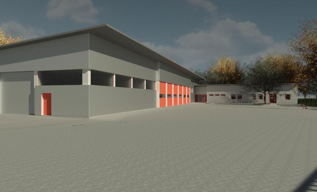
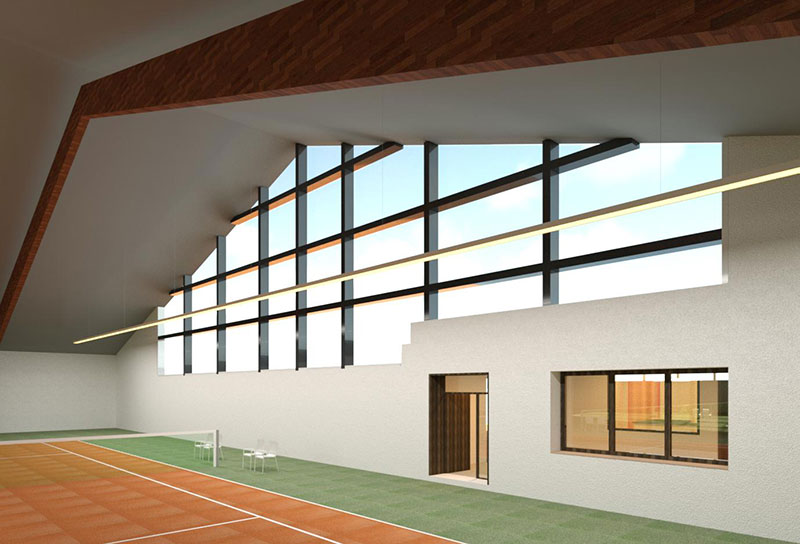
| Visualisation | The spatial presentation of a complete building on the basis of 2D plans requires a good imagination of the customer. For visualisation purposes, sketches are often made, models built and pictures rendered. | The 3D model is perfectly suited for visualisation. In combination with a point cloud and the scanned area around the object, the customer can be shown how the finished house will later look in the surrounding area. You can present sun studies or the later finished furniture. Thanks to VR technology, the customer can also move through the model by himself and thus understand much better what he will be proposing. What used to be elaborately shown with individual photos or manually built models can now be generated on the computer. Should the customer not like something, it can be changed quickly and easily on the PC. |
| 2D modelling | 3D modelling | |
|---|---|---|
| Data size | Small Due to the pure geometry data and the simple drawing elements, the 2D data usually does not become as large as the 3D model data. The exchange and shipping are easy and uncomplicated. | Large to very large! Due to much more information in the model plus the third dimension, the data of 3D models becomes much larger than the 2D data. These file sizes could make the exchange between the project partners difficult without prior agreement. Experience shows that external data carriers, a separate server or cloud-based solutions (e.g.: BIM 360, SharePoint) offer good exchange possibilities. |
Example small building:
| 2D CAD file | 3D CAD file | |
|---|---|---|
| Storage space | 0,6 MB | 130 MB |
| 2D modelling | 3D modelling | |
|---|---|---|
| Exchange format | DXF, DWG… very simple and readable by any software | IFC – The exchange format for 3D models is constantly evolving and improving. When using the 3D models as reference models, there are hardly any changes in performance. For direct import, the export and import settings should be checked and defined carefully. |
Conclusion
What type of modelling should you use now? Both analysis methods have their own authorisation and can be used effectively. Which method is the most effective for your project depends on many factors. What information do you need, what requirements do the individual project partners have and how much are you willing to invest? Do you need a visualisation or do you want to process the data later? Do the project partners work on site or is a digital twin required?
In more and more areas, the advantages of 3D modelling prevail and are being recognised. Standards and analysis strategies can be discussed and defined by a thorough project consultation before the start of the modeling process.
Should you nevertheless have doubts about which modelling method is suitable for your next project, do not hesitate to call us at +49 (0) 351 - 82 87 33 60 or send an e-mail to modellierung@laserscanning-europe.com. We will be glad to help you.
Your Laserscanning Europe team

Are you interested in our modeling service?
> Call us @ +49 (0) 351 - 82 87 33 60