As-built modelling of half-timbered houses in Revit

Title3D-Modellierung einer historischen Fachwerkscheune für Umbau und Umnutzung
Im vergangenen Jahr modellierten wir für Herr Adrian S. Rauer, Freier Architekt, eine historische Fachwerkscheune. Die 3D-Modelldaten sollen als Bestandsunterlagen für die Umbauplanung und Umnutzung verwendet werden. Ziel war es, die Scheune verformungsgerecht zu modellieren und die Daten im Format IFC zu übergeben. Das 3D-Aufmaß wurde durch den Kunden mittels Scanning selbst durchgeführt und uns als registrierte Punktwolke im Format E57 übergeben.
Last year, we modelled a historic half-timbered barn for Mr. Adrian S. Rauer, freelance architect. The 3D model data is to be used as as-built documentation for the conversion planning and change of use. The aim was to model the barn in a deformation-true manner and to transfer the data in IFC format. The 3D measurement was carried out by the customer himself by means of scanning and handed over to us as a registered point cloud in E57 format.
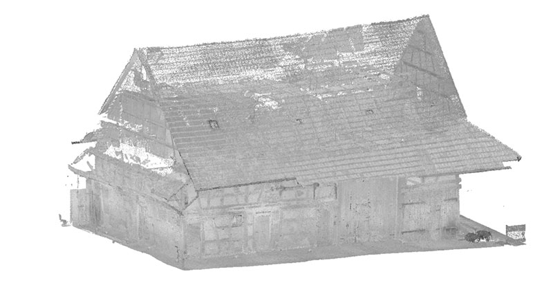
Throughout the entire barn, there were almost no straight walls, timbers or pillars. Even doors and windows were crooked, which was a particular challenge for us as modellers.
Together with the customer, we discussed the requirements for the model, including the necessary accuracies and tolerances. This agreement is an indispensable part of the modelling process for us, as our customers have different requirements for their models (LOD 100...LOD 350) and the results can vary greatly according to customer requirements.
The modeling process in Revit
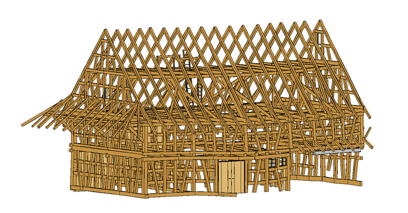
We developed a modelling process that allows us to visualise all objects in a controlled and complete way. For this purpose, we divided the barn into different work areas and modelled according to the following scheme:
- Definition of the modeling levels in Revit
- Modelling of the horizontal beams (wall plates, top plates, ceiling beams, etc.) as Revit element: beam
- Modelling of the vertical pillars (studs, struts, etc.) as Revit element: pillars
- Positioning of the connecting transoms in the truss as Revit element: beam project family
- Modelling of the inclined beams in the roof as Revit element: pillars
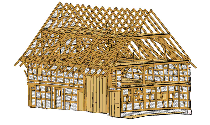
- Positioning of walls, windows, doors and ladders
- Definition of the roof
Aspects to be considered in the modelling of the existing building
Revit has been developed for BIM-compliant design. Thus, the representation of components that do not have a regular geometry is not necessarily intended in Revit.
Due to the high deformation we had to split the beams into sections and tilt the pillars in two levels. This approach enabled us to represent reality almost identically.
For the inclined roof beams, we decided to use pillar elements because the beam connection options of the project side could be used here quickly, easily and in a single work step.
For the small connecting transoms in the truss, we created our own families of beams, which enable the exact connection to the inclined pillars (struts).
The walls (space bettween timber frames) were modelled almost exclusively as project elements.
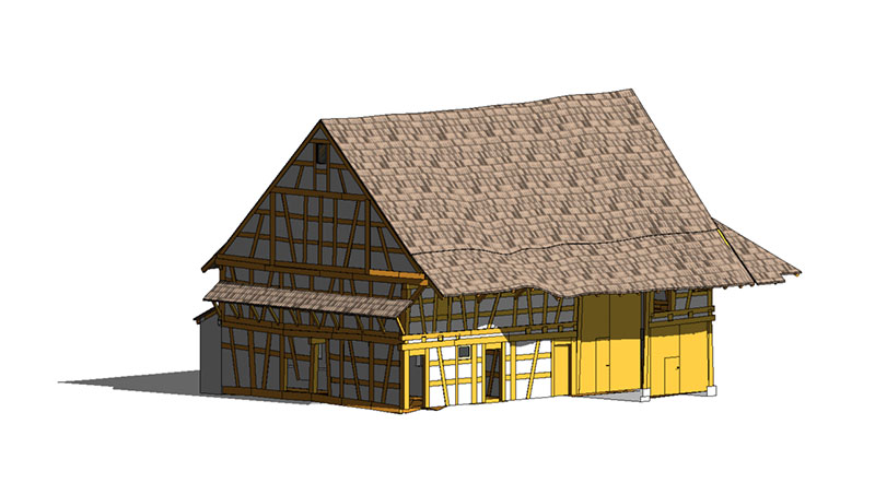
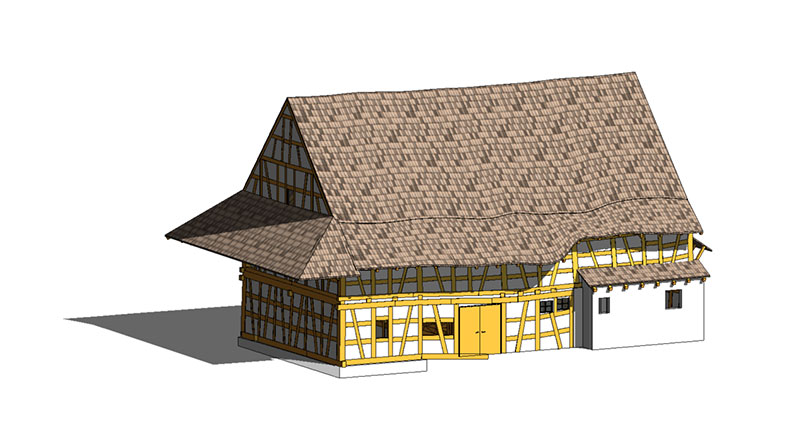
The modelling of the roof was complex. As can be seen very clearly in the model view (Fig. 4), it is a very crooked and inclined cover. We divided the roof into partial roofs and were thus able to work on approx. 2/3 of the area with the usual and common roof modules. The wavy roof area (Fig. 4) challenged our creativity. We used free body shapes and placed the roof areas above them.
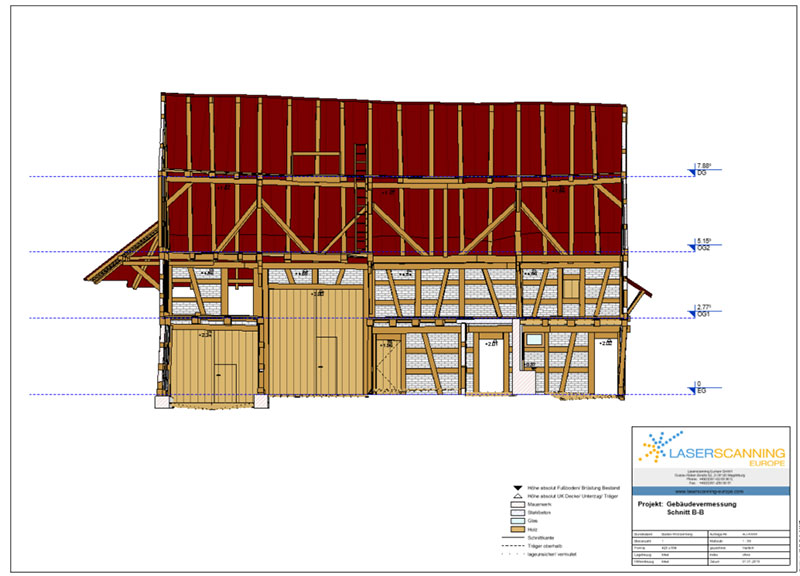
It took us two weeks for the modelling and - in addition to the model - we handed over derived floor plans, sections and views of the half-timbered building.
Conclusion on the Revit modelling of half-timbered houses
The modeling of complex geometries is also possible in Revit; very accurate BIM models of the building can be obtained. However, the modeler needs some prerequisites for this job. Most importantly, the BIM modeler must have a very good knowledge of Revit. This requires a good training and some experience in as-built modeling. The modeler needs to understand which Revit tools are best and fastest to recreate the deformed geometries in Revit. In addition, together with the customer, he must also select a LOD that can still be implemented with a reasonable amount of effort.
Contact from Adrian S. Rauer: