Parametric modeling with user-specific data
TitleWeiterentwicklung der 3D-Modellierung: Präzisere Daten für komplexe Infrastrukturen
Viele unserer Kunden haben in den letzten Jahren die Vorteile der 3D-Modellierung erkannt und nutzen diese Modelle aktiv in der weiteren Datenverarbeitung. Bisher lag der Fokus hauptsächlich auf der Gebäudegeometrie. Mittlerweile erreichen uns immer mehr Anfragen zur Erfassung von benutzerspezifischen Daten, z. B. technische Gebäudeausstattung, abwassertechnische Anlagen, unterirdische Versorgungskanäle, etc. Die Informationen in den Modellen werden immer vielfältiger und detaillierter und erfordern von den Modellierern zunehmend Fachwissen und modellierungstechnische Kniffe und Fertigkeiten. Unser aktueller Anwenderbericht ist aus dem Bereich der Abwassertechnik. Die Weiterentwicklung der 3D-Modelle mit ihren Vor- und Nachteilen sowie verschiedene Fragen zur Modellierung werden nachfolgend an diesem Projekt erklärt, analysiert und betrachtet.
Many of our customers have identified the advantages of 3D modeling in recent years and actively use these models in further data processing. So far, the focus has been mainly on building geometry. In the meantime, we are receiving more and more requests for the creation of user-specific data, e.g. technical building equipment, wastewater facilities, underground supply channels, etc. The information in the models is becoming more and more versatile and detailed and increasingly requires expert knowledge and modelling tricks and skills from the modellers. Our current case study is from the field of wastewater technology. The further development of 3D models with their advantages and disadvantages as well as various questions regarding modeling are explained, analyzed and considered in this project.
Task and data basis
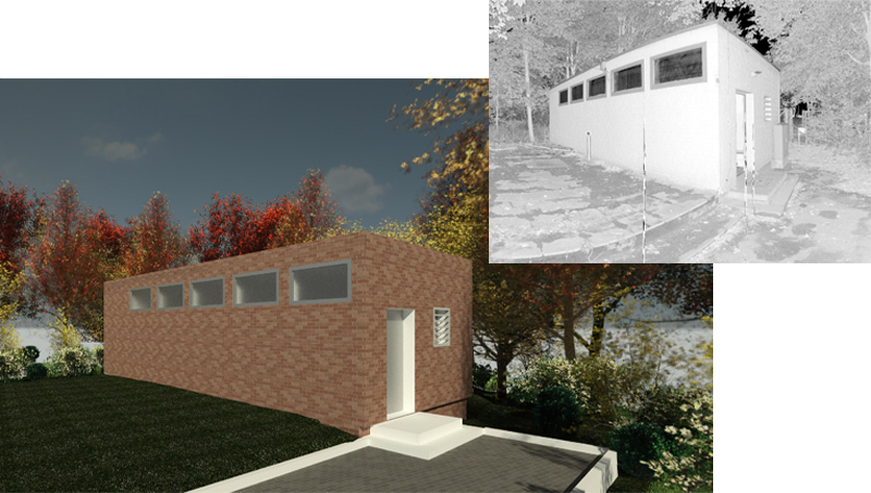
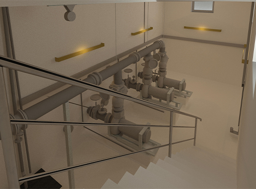
The scan data of a pumping station were processed to a complex and very detailed as-built model. The pumping station consists of three structural levels with different sewage engineering systems, electrical engineering, plumbing and ventilation/air conditioning technology. The 3D model is to be used subsequently for reconstruction planning. Further considerations will focus on the elements of the sewage technology.
The scan data was captured and registered with a terrestrial laser scanner. The georeferenced point clouds were then parametrically modeled with the software Autodesk Revit.
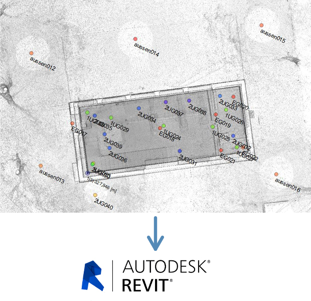
The modeling was done according to the principle of "big into small". Starting with the elements "construction" the pumping station was refined step by step and filled with technical information.
Classic/direct or parametric modeling
The question of which type of modeling should be used plays a major role in project management. While only a few years ago only pure geometry (classic and/or direct modeling) could be modeled, today it is possible to assign and define parameters and dependencies (parametric modeling). In practice, there is usually no "either-or" principle. The most economical results are achieved by the clever combination of both types of modeling.
Classic and/or direct modeling
This modelling type focuses on pure geometry. The objects are represented by edge, surface and solid models. By changing the basic geometry (e.g. by scaling, stretching, rotating, etc.) the objects are acquired realistically and without dependencies to each other. In practice, this type of modeling is very popular for complex objects or interfering edge models and is often used because "as-built" modeling can be done very quickly and easily.
Parametric modeling
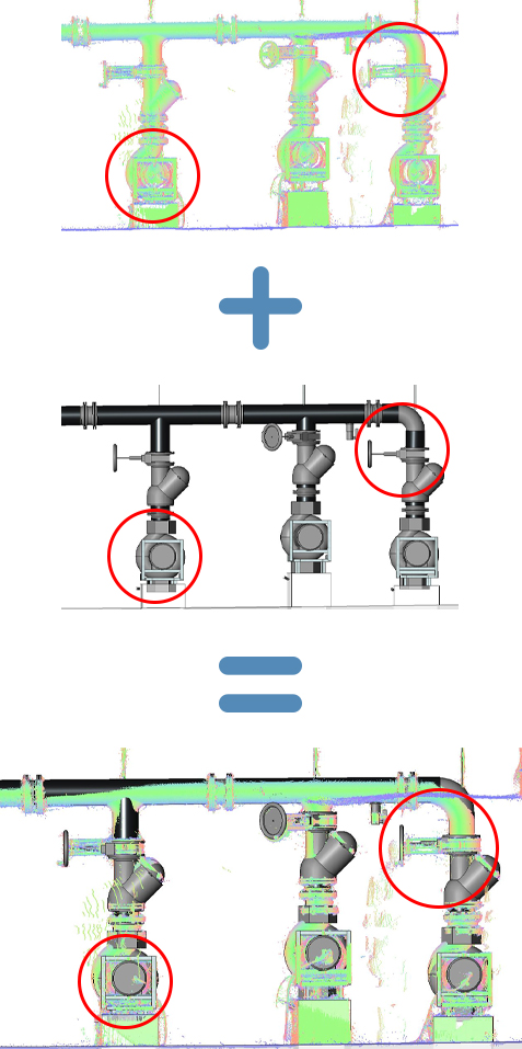
In parametric modeling, the objects are defined with attributes (e.g. material, dimension, color) and dependencies among each other in addition to the parameters of pure geometry. The control of the objects is thus exclusively done via parameters. Windows are related to walls, railings are related to stairs and fittings are related to pipes. A change of the main elements results in a change of the sub elements. In contrast to direct modeling, the creation of parametric elements requires good 3D modeling knowledge and requires some experience and practice. The generation of a parametric object can be illustrated very well by a Revit family element (flange).
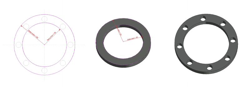
Starting with a sketch, the geometric parameters are then added (e.g. height, width, radius, rotation). By assigning countless additional attributes, the objects created in this way can be refined to form a unique model element (e.g. color, material, manufacturing number, year of installation, etc.). When this example element is placed on a pipeline, dependencies are created. These associativities can be used to move e.g. entire piping systems including fittings.
Modeling of fittings
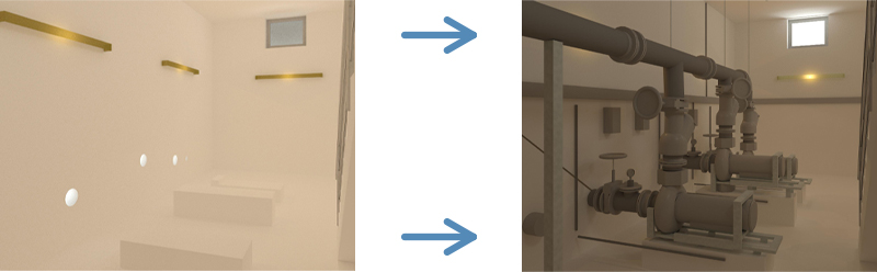
A challenging task was to model the various fittings and pipelines "as-built". The sometimes very close sequences of various components can only be modeled to a limited extent with the Autodesk Revit fitting libraries. Without changing and/or extending the standard elements, almost no fitting could be captured with an existing library element.
These individual adjustments cost a lot of time. For this reason, it is important to clarify in advance how relevant the 100% realistic representation is for further data processing. Intelligent generalization approaches are very helpful and target-oriented here (see following example).
Modeling and accuracy
Our customers want their facilities to be modelled realistically. When asked about the accuracy of the model, the answer frequently given in practice is: "As accurate as possible! ...but is that really always advisable?
In our project, there were some examples that consider these accuracy requirements from different perspectives and reflect that "as accurate as possible!" is not always the best decision in every case. A good consultation in advance often changes this statement. The accuracy requirements are then in a balanced relationship to the effort and benefit.
Project example 1: Sagging of pipelines (parametric modeling)
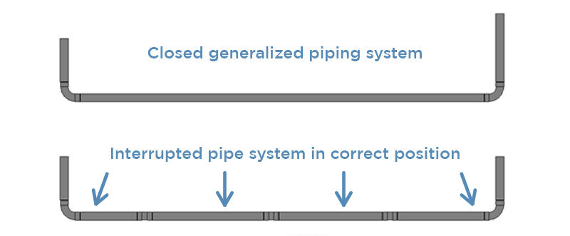
Sagging in the pipelines is particularly noticeable in old facilities and pipelines. Should or must these be modeled? Is the information important for the customer? Usually, the closed piping systems are destroyed with a deformation-compliant representation, because the reality has to be represented with segments.
Project example 2: Curved sections and bends with small radii
Parametric modeling always means modeling according to basic mathematical rules and routines of the software. If a curve cannot be created mathematically, it is only possible to place it with tricks and knacks. In most cases, this interrupts or separates the parametrically continuous piping system. In practice, creative installation solutions are often found which can only be presented to a limited extent with the software tools. A balanced degree of generalization is required and necessary here.
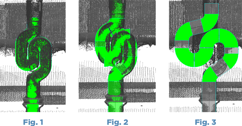
In Fig. 1, the pipe bend was modeled classically (sweep function). The image corresponds exactly to the geometric reality. However, this type of modeling is not related/dependent on the parametric adjacent pipe elements. A later change to the pipe system (e.g. change of dimension) requires an adaptation of the classic modeling (time!).
In Fig. 2, the parametric components of the Autodesk Revit software were used and manipulated in such a way that the image almost corresponds to reality. Due to the basic mathematical rules of pipe generation, the closed piping system had to be interrupted. Connecting intermediate pieces were deleted and the elements had to be moved into each other. This illustration does not appear very nice optically, but is created with parametric elements. Changes to the pipe system are adopted by all elements.
In Fig. 3, the entire curvature is modeled with the components from Autodesk Revit. The piping system is closed and working. It can then be used for analyses and hydraulic calculations. However, the figure does not correspond to reality.
Which illustration is the right one for the customer? All three have their justification and are neither right nor wrong. In practice, the form of representation and modeling type will vary depending on the way the model is used.
Modeling and information density
Which information and level of detail does the customer need for his model? Are electrical engineering, sanitary and ventilation/air conditioning technology required in addition to the "construction" and the "waste water technical elements"? All this information could be taken from the point cloud and modeled – but does the customer need this information? Often the models are blown up by unneeded data and their performance is slow and inflexible. The project handling should always be considered in advance under the cost-relevant aspects of information density, data sizes and further processing.
Modeling and expertise
When modeling specific facilities, the CAD user is faced with special challenges. Often, a certain basic knowledge must be acquired in advance in order to be able to carry out the modeling almost professionally.
In practice, different mediums come together (e.g. drinking water, cooling, heating, electrical engineering, etc.). To what extent does the modeler have to apply interdisciplinary knowledge? Our experience has shown that it is advisable to have the models provided specified or verified by the appropriate experts.
With parametric modeling, the components can be described and specified clearly. As a non-specialist, these determinations and definitions are very difficult, which can be clearly seen in the following example.
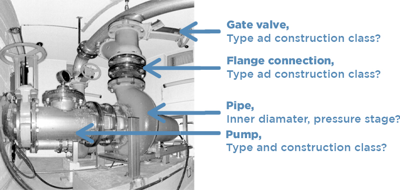
The definition of a gate valve is still relatively simple, but the allocation of the different types and construction classes already requires specialized knowledge.
The Autodesk Revit libraries offer a variety of pipe accessories. Gate valves, valves and many other fittings are available in a wide variety of types and shapes.
The backwash filter shown below is available in numerous variations, always depending on material, function, pressure level, dimension, manufacturer, etc. But the decision which type – under all professional aspects – is the 100% right one to use is very difficult. In practice, the modeler can only extract the interfering edges from the scan data. Happy to have found a suitable element, the geometrical extension is now primarily correct, but what about the parameters (attributes)?
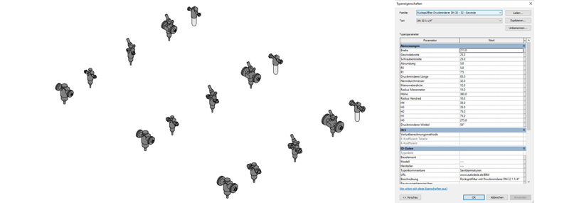
An adaptation/deletion of unreliable parameters would be possible, but it is also very time-consuming and usually bears no relation to the actual model statement. Without the support of experts, communication in advance and the subsequent technical adaptation and correction during further processing, misinterpretations of the models could result.
Export of 3D models
Due to the further development of the interfaces for export, attributes and classifications can be transferred in addition to the geometry data. The models are subsequently used, shared and regarded as binding by different departments. The end user has often never discussed the data set with the modeler. Thus, information is partly taken from the models that the modeler is not able to provide 100%.
Without transparent communication and without a clear definition of modeling standards, information could be lost or not properly classified.
Conclusion
Professional consulting, communication and transparency in project management are the cornerstones for successful modeling. The concept should be created and executed based on the factors time, money, effort and benefit.
Discuss as many of the preceding aspects as possible with your customers in advance and thus ensure a smooth project flow.
Laserscanning Europe – Your partner in modeling
Do you have questions about 3D modeling? Would you like to carry out a project together with our experienced modelers? Simply contact us by phone at +49 (0)351 82 87 33 60 or by e-mail at info@laserscanning-europe.com. We will be happy to advise you.