Planning in harmony with the surrounding environment

TitleRealitätsnahe Planung – Wie 3D-Modelle und Bestandsscans die Architektur optimieren
Zu den Aufgaben eines Planers gehört, seinen Kunden einfach, schnell und realistisch eine Sanierung, Neubauplanung oder Gebäudeerweiterung im realen Bestand zu präsentieren. Viele Planungsmodelle existieren bereits in 3D und werden zu Präsentationszwecken stilistisch aufbereitet und verschönert. Aber wie sieht die Planung im realen Gelände aus? Fügt sich das neue Gebäude in ein bestehendes Bebauungsgebiet? Wie ist die Höhenentwicklung? Wie sind die Dimensionen? Wo entstehen Licht und Schatten? Und welche Baumaterialien passen am besten in die Umgebung? Alle diese Fragen lassen sich leicht mit der Kombination aus 3D-Modell und Bestandsscan (Punktwolke) klären und visualisieren.
An einem unserer aktuellen Kundenbeispiele lässt sich der Ablauf von der Datenübernahme bis hin zur fertigen Präsentation gut erläutern. Unsere Kunden, Herr Jörg Schwarzer von scanhoch3 und sein Geschäftspartner Hr. Gunnar Salomon, Fa. Salomon Bau traten mit der Idee der Datenkombination an uns heran. Als Grundlage wurden das geplante 3D-Modell im Format IFC, die Materialien der Fassaden, die geometrische Einpassung des Neubaus in den Bestand (z. B. Lageplan zum Bauantrag, Einpassungsskizzen, Höhenbezug, etc.) und eine Punktwolke der Umgebung übergeben. Unsere Aufgabe war es, die Daten für die Präsentation in einem relativ engen Zeitfenster aufzubereiten.
TitleAblauf
Für die Aufbereitung der Daten haben wir die Produkte von Autodesk verwendet. Das 3D-Modell und die Punktwolke lagen in verschiedenen Koordinatensystemen (lokal/georeferenziert) vor. Die Punktwolke wurde mittels terrestrischem Laserscan (-> Tipp 1) erstellt.
Datenaufbereitung in Autodesk Revit:
- Import des geplanten 3D-Modells
- Festlegung eines geeigneten Referenzpunkts in der Punktwolke
- Ausrichtung des 3D-Modells mit Hilfe des Referenzpunkts
- Import der Punktwolke
Datenkombination in Autodesk Navisworks Manage:
- Erstellung eines neuen Projekts
- Import des Revit-Modells und der Punktwolke
- Korrektur/Änderung (bei Bedarf) der Materialien
Erstellung der Präsentation in Autodesk Navisworks Manage:
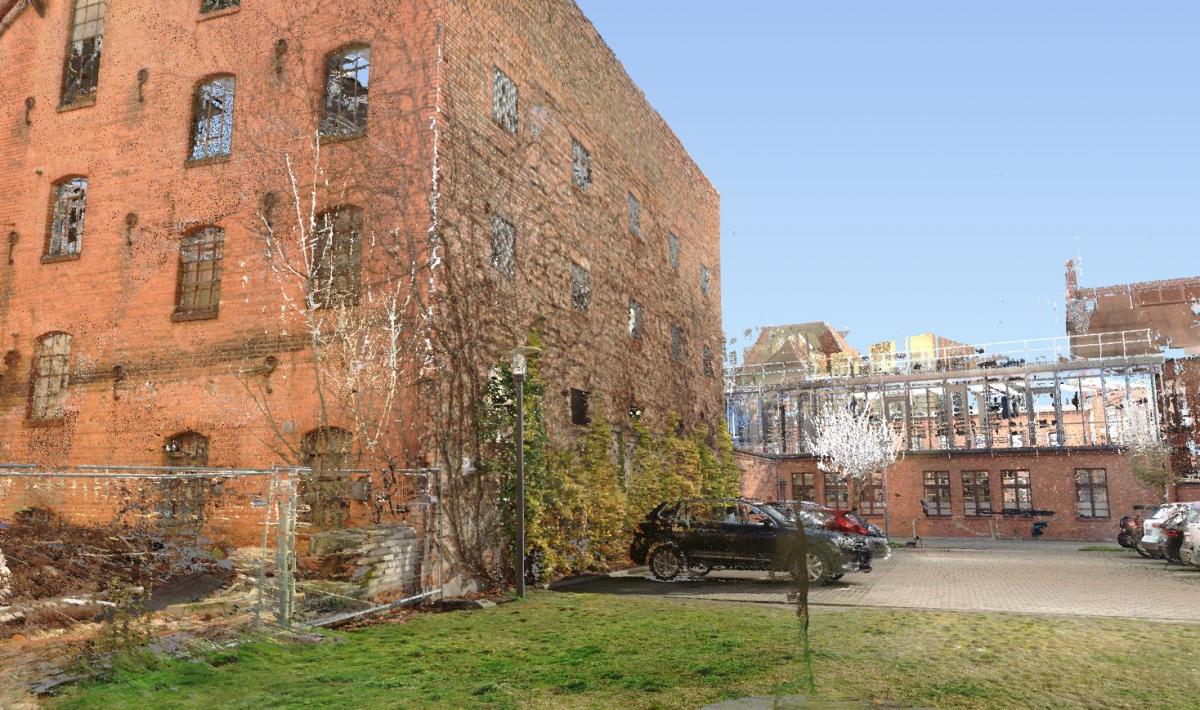
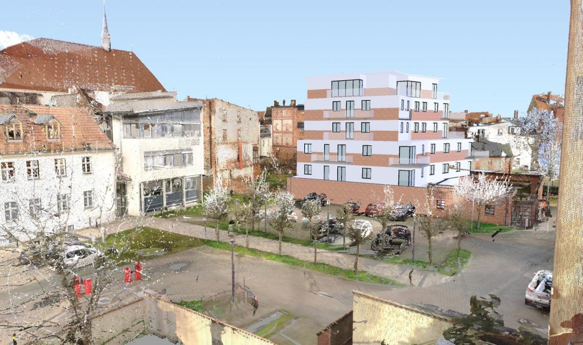
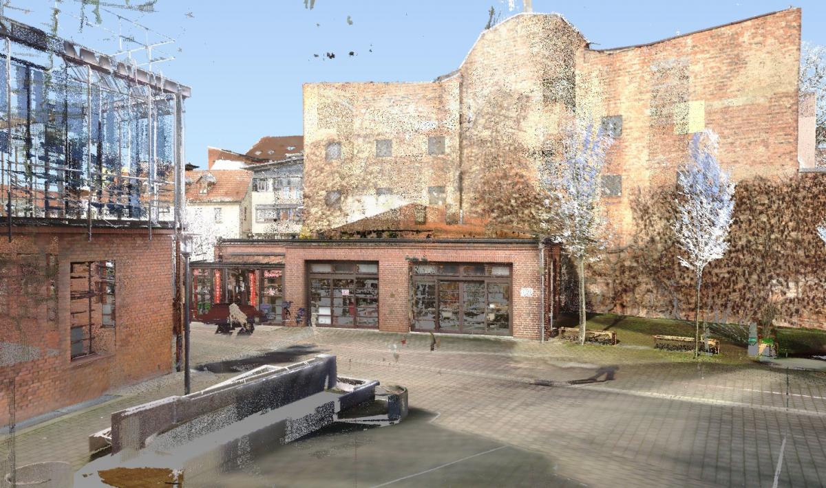
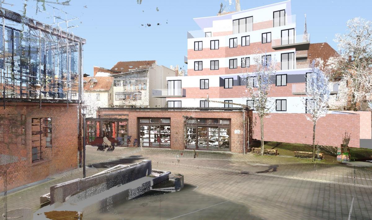
- Erzeugung der Ansichtsstandpunkte und Perspektiven (z. B. Abb.1/1a)
Übergabe der Daten zur Präsentation in die kostenfreie Software Autodesk Navisworks Freedom:
- Export des Autodesk Navisworks Manage Projekts als NWD-Datei (-> Tipp 2)
Tipp
- Je höher die Auflösung beim Scan gewählt wird, umso realistischere Punktwolkenergebnisse (aber auch umso größere Datenmengen) werden erzielt. Hier empfiehlt sich ein guter Mittelwert.
- Bei der Arbeit mit Punktwolken entstehen meist große Datenmengen, die bei Präsentationen zu langen und unschönen Wartezeiten führen können. Um die Präsentation flüssig und professionell durchzuführen, sollten bereits vor der Präsentation alle Ansichtsstandpunkte geladen werden.
TitleFazit
Die Kombination der real gescannten Umgebung mit dem 3D-Modell ermöglicht allen Beteiligten das geplante Bauvorhaben schnell im Konsens mit der Nachbarschaft zu betrachten. Die Zuschauer erhalten einen lebendigen und realitätsnahen Eindruck. Sie können das Projekt perfekt beurteilen, den Bau von jeder beliebigen Seite und aus jeder Perspektive betrachten, Ideen- und Änderungswünsche beisteuern, knifflige Bereiche kritisch begutachten und weitere anschließende Konzepte (z. B. Verkehrserschließung, Bewirtschaftung, Grünanlagen, etc.) entwickeln.