Scanning elevator shafts using a horizontal tripod

TitleVermessung von Fahrstuhlschächten
Bei diesem Projekt werden zwei Fahrstuhlschächte in einem Quartier in der Hamburger Innenstand (nahe der Binnenalster) vermessen. Der Gebäudekomplex ist etwas in die Jahre gekommen und wird deshalb von Grund auf saniert. Das Gebäude erstreckt sich über 7 Geschosse inklusive Keller. Die beiden vorhandenen Fahrstuhlschächte sind komplett entkernt. Die beiden alten Aufzüge wurden vollständig entfernt. Die Zugänge zum Schacht auf jeder Etage sind etwa halbhoch mit einer hölzernen Absturzsicherung versehen.
Vermessung von Fahrstuhlschächten
Messumgebung
This project involves surveying two elevator shafts in a district in Hamburg. The building complex is quite outdated and is therefore being renovated from the ground up. The building extends over 7 floors including the basement. The two existing elevator shafts have been completely gutted. The two original elevators have been completely removed. The entrances to the shaft on each floor are fitted with wooden guardrails about halfway up.
Problem & Task
The two elevator shafts are being surveyed to determine the possible dimensions of the new elevators. The possible inclination of the shaft is particularly interesting. The elevator must be able to move vertically in the shaft. An inclined position of the shaft therefore reduces the maximum possible footprint of the future elevator. Equally important is the determination of the smallest cross-section in the shaft, colloquially the "narrowest" point in the shaft, since this dimension also limits the maximum floor space of the elevator. Finally, the total height and the positions of the accesses to the elevator must be determined. From the surveyor's point of view, the measurement of the elevator shaft is problematic since conventional measurement configurations produce either a very non-homogeneous or an incomplete point cloud.
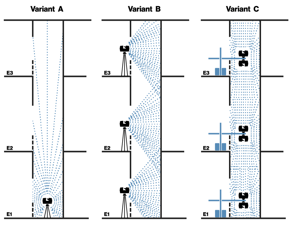
The point cloud becomes non-homogeneous if only one viewpoint is possible at the bottom of the shaft. The point density in the lower part of the shaft is then much greater than in the upper part. The point density decreases with increasing height of the elevator shaft (variant A).
The point cloud becomes incomplete if the scanner is placed on the individual floors directly at the entrance to the elevator shaft. Because measurements are taken laterally into the shaft, there are always areas that remain "invisible" to the scanner (variant B).
In order to solve the problems arising from variants A and B, the LSE horizontal tripod is used. With the help of the special tripod, the scanner can be placed safely and stably in the center of the shaft. The laser scanner can be mounted conventionally in an upright position, and overhead mounting is also possible without any problems. The result is a point cloud that is as homogeneous as possible and also complete. The problems from variants A and B are thus eliminated here (variant C).
Equipment
Procedure of the survey
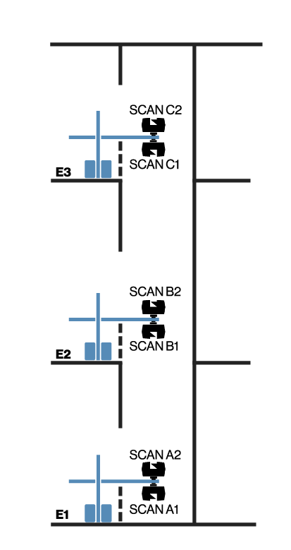
On each floor, two scans are made using the horizontal tripod: one scan in normal orientation, and one scan mounted overhead. For a normal elevator shaft, 1/5 of full resolution is suitable, as well as 3x quality. With these settings, a scan takes about 3 minutes. Converting from upright mount to overhead mount also takes about 3 minutes. Tripod setup per floor takes about 6 minutes. Thus, one floor takes about 15 minutes; then you can move to the next floor. Thus, for the total of 6 floors, about 90 minutes were needed. When surveying, it is important to ensure that the laser scanner is not mounted at an angle of more than ±3 degrees so that the tilt sensor can work optimally. After all, the inclination sensor data can be used to determine the inclined position of the shaft.
Workflow of the analysis
The individual scans are combined (registered) using the Cloud2Cloud algorithm in the FARO SCENE software. Alternatively, Scantra can also be used
After the scans are successfully registered, floor plans and sections are generated using PointCab Origins:
- Sections to determine the inclination
- Floor plans on each floor level to determine the minimum cross-section
- Floor plans and sections in the area of accesses to determine their dimensions and positions.
The floor plans and sections are now imported into AutoCAD and drawings are created from them. Alternatively, it is also possible to work with the point cloud in AutoCAD. This is done by importing it in RCP format and then working with the point cloud clipping tools in AutoCAD.
Results
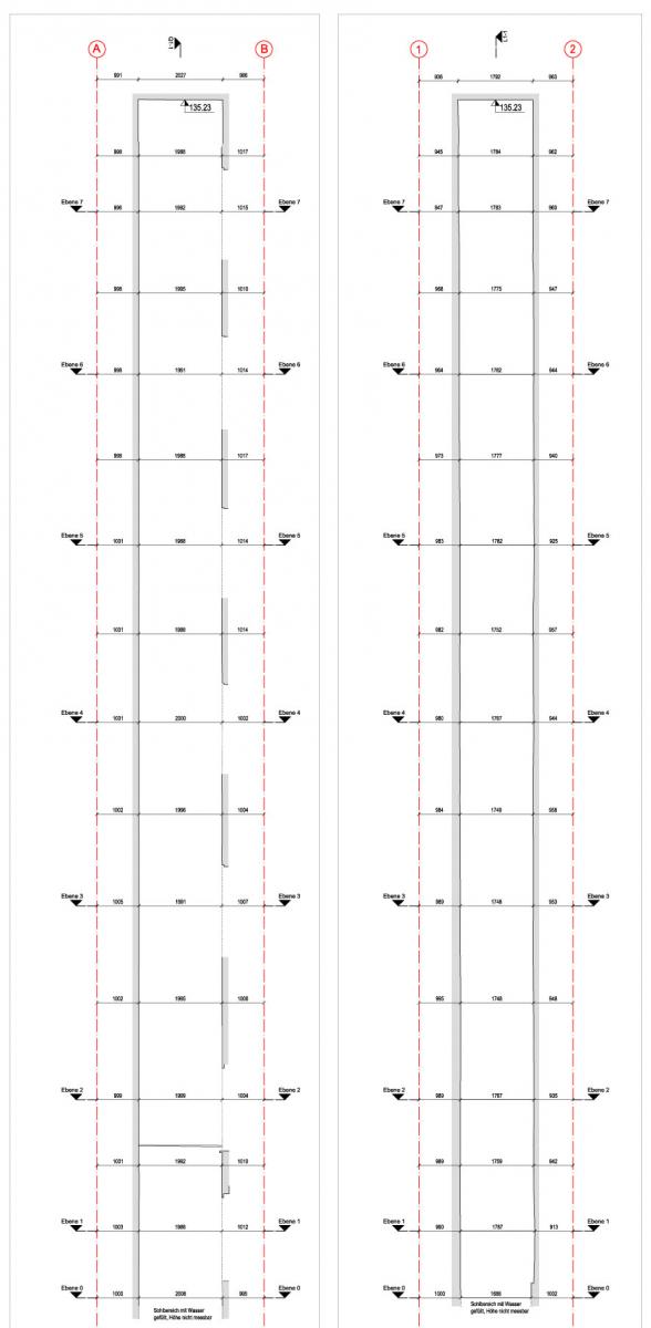
By making individual slices through the entire shaft, it was possible to determine the minimum cross-section. In the end, this minimum cross-section defines the maximum size of the future elevator.
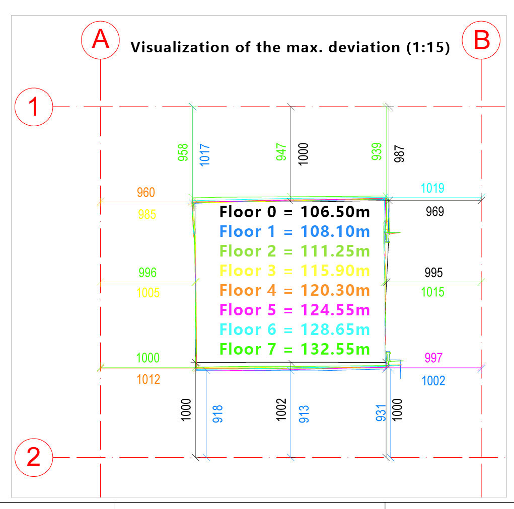
The two sectional views also show how the course of the shaft develops over the height. The axis grid serves as a reference from which the distances to the inner wall of the shaft are determined.
Get in touch!
+49 391 62 69 960 | +49 7153 66 29 112 | +49 2151 60 32 955
Write an e-mail: