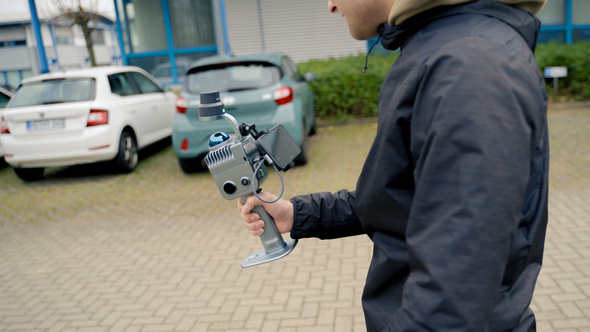
How to georeference a point cloud?

TitleWhat does georeferencing mean?
Each point cloud initially represents only a collection of surveying points in a local coordinate system. However, in order for this data to be combined with other sources – such as CAD plans, UAV images or GNSS surveys – it must be transferred to a higher-level geodetic coordinate reference system. This process is called georeferencing.
Precise georeferencing is the basis for accurate surveying and planning processes. Whether in the BIM environment, in the documentation of industrial plants or in forestry and agriculture, only correctly georeferenced point clouds enable reliable further processing and evaluation.
In this article, we show you how to georeference point clouds easily and accurately – and which methods and tools are particularly suitable for this.
TitlePoint clouds & coordinate systems – The basics
Before a point cloud can be georeferenced, it is important to understand the basics of coordinate systems and point cloud structures. It should be noted that georeferencing does not affect the measurement accuracy of the individual scan points, but rather their absolute positional and height accuracy in the higher-level coordinate system. It therefore determines how correctly the point cloud can be spatially classified and linked to other geodata.
What is a point cloud?
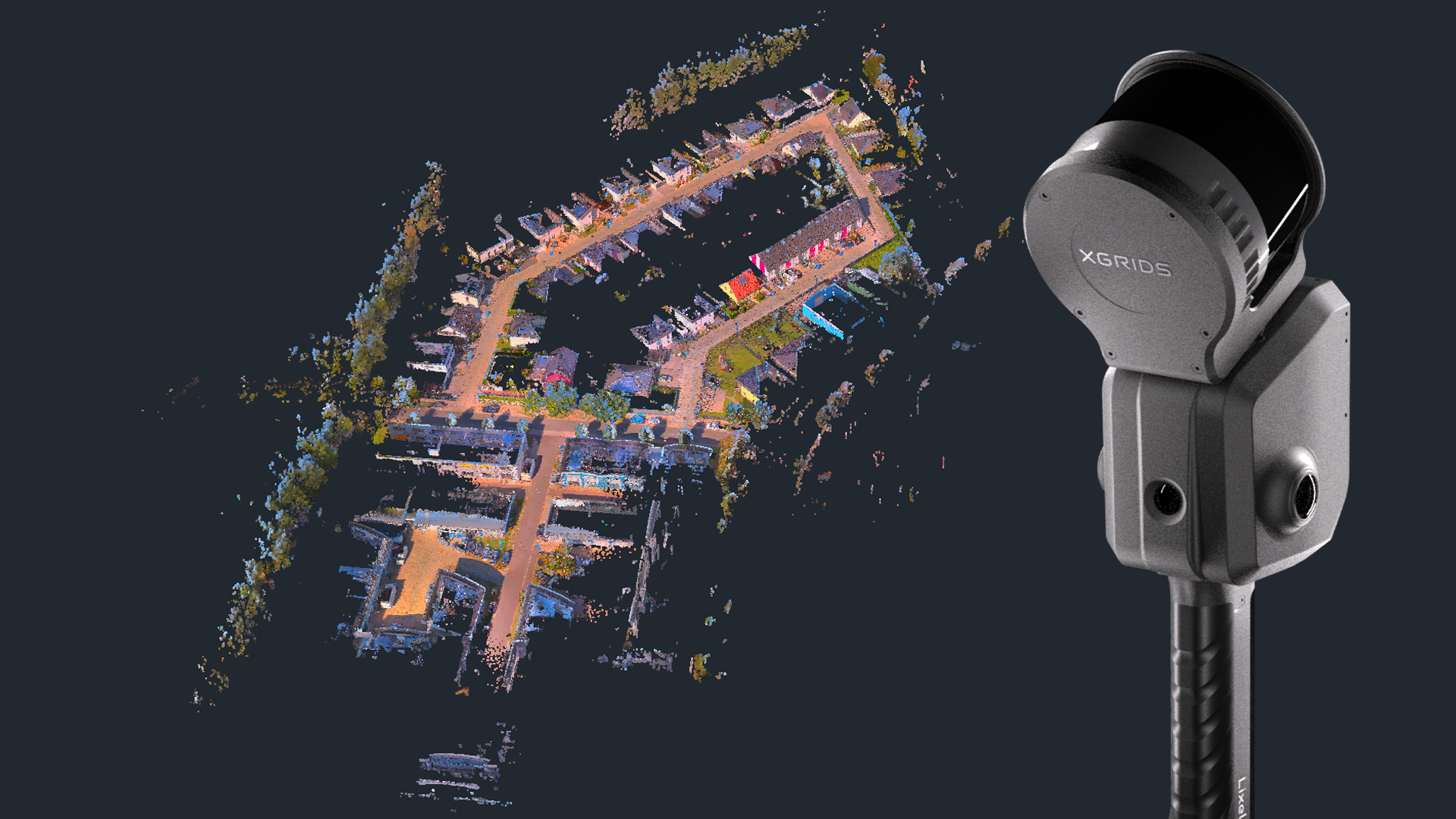
A point cloud consists of a large number of individual survey points that are captured by laser scanning or photogrammetric image analysis – either terrestrially or airborne, for example using a drone (UAV). Each of these points contains information about its spatial position (X, Y, Z) – often supplemented by colour information (RGB) or intensity values.
In many cases, these points are initially available in a local coordinate system that refers to the origin of the scanner. This means that the point cloud knows its internal geometry (relative accuracy) but not its position on earth.
Local vs. Global coordinate system
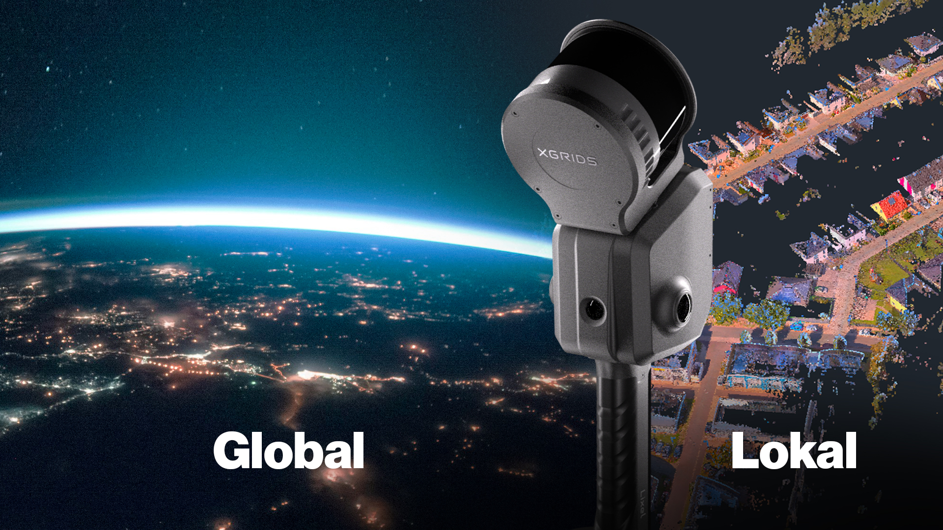
Local coordinate system
- The origin is usually the position of the scanner or the first measurement.
- Axes are aligned arbitrarily.
- Used within a project (e.g. building scans) where the absolute position is unimportant.
- Advantage: Quick and easy to create.
- Disadvantage: Direct integration into higher-level geodetic reference systems and GIS environments is not possible without additional transformation.
Global coordinate system
- Refers to an earth-based coordinate reference system, such as UTM (Universal Transverse Mercator) or Gauss-Krüger.
- Points have real geographical coordinates (e.g. ETRS89 / UTM Zone 32N).
- Allows the combination of multiple data sets, e.g. drone flights, terrestrial scans and GNSS measurements.
- Necessary for GIS analyses, mapping or building documentation in the national reference system, as well as for official planning and approval procedures.
Reference points & control points
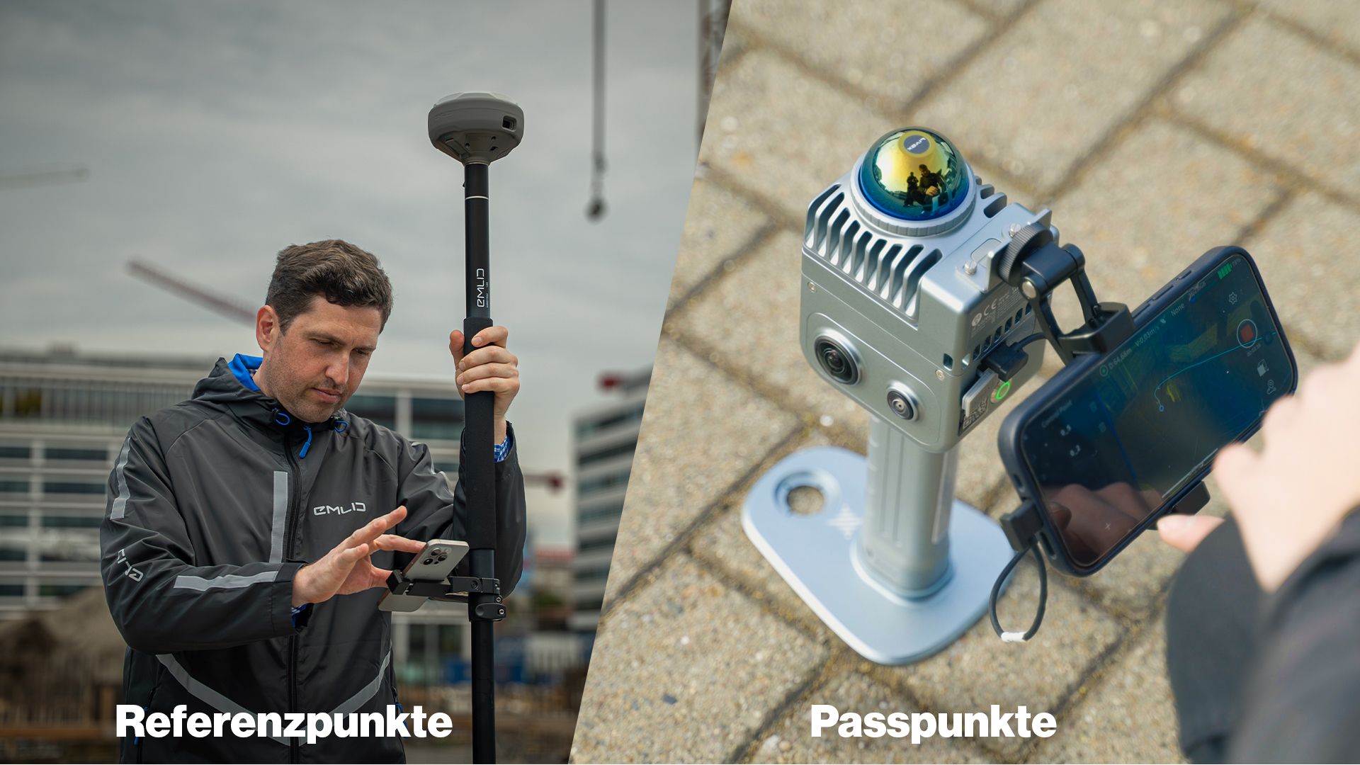
In order to transfer a point cloud from a local to a global coordinate system, known points in the terrain or on the object are required:
- Reference points: Measured points with known coordinates in a higher-level reference system (e.g. GNSS or total station).
- Control points: Points that can be identified both in the scan and in the measurement data.
By assigning these points, a mathematical transformation (e.g. Helmert transformation) is calculated that correctly positions and aligns the point cloud in space.
TitleMethods of georeferencing
The georeferencing of a point cloud can be carried out in various ways, depending on the hardware used, the desired accuracy and the time available. The four most common methods are presented below.
Georeferencing using targets
One of the most classic and precise methods is georeferencing using targets (also known as reference marks or target marks).
Before data is collected in the field, physical targets – such as spheres, checkerboards or stickers – are distributed in clearly visible positions. These targets are measured precisely using a GNSS receiver or a total station so that their global coordinates are known.
When the point cloud is imported into the analysis software (e.g. FARO Scene or Trimble RealWorks), the scanned target positions are automatically recognised and assigned to the measured coordinates.
This allows the point cloud to be precisely transformed into the global coordinate system.
Advantages:
- Very high accuracy (millimetre to centimetre range)
- Independent of GNSS coverage (can also be used indoors)
- Ideal for technical surveying and plant surveys
Disadvantages:
- Additional effort required for setting up and surveying the targets
- Line of sight between scanner and targets required
This method is particularly suitable for building surveys, industrial plants and engineering surveying, where precision is a top priority.

Direct georeferencing using GNSS
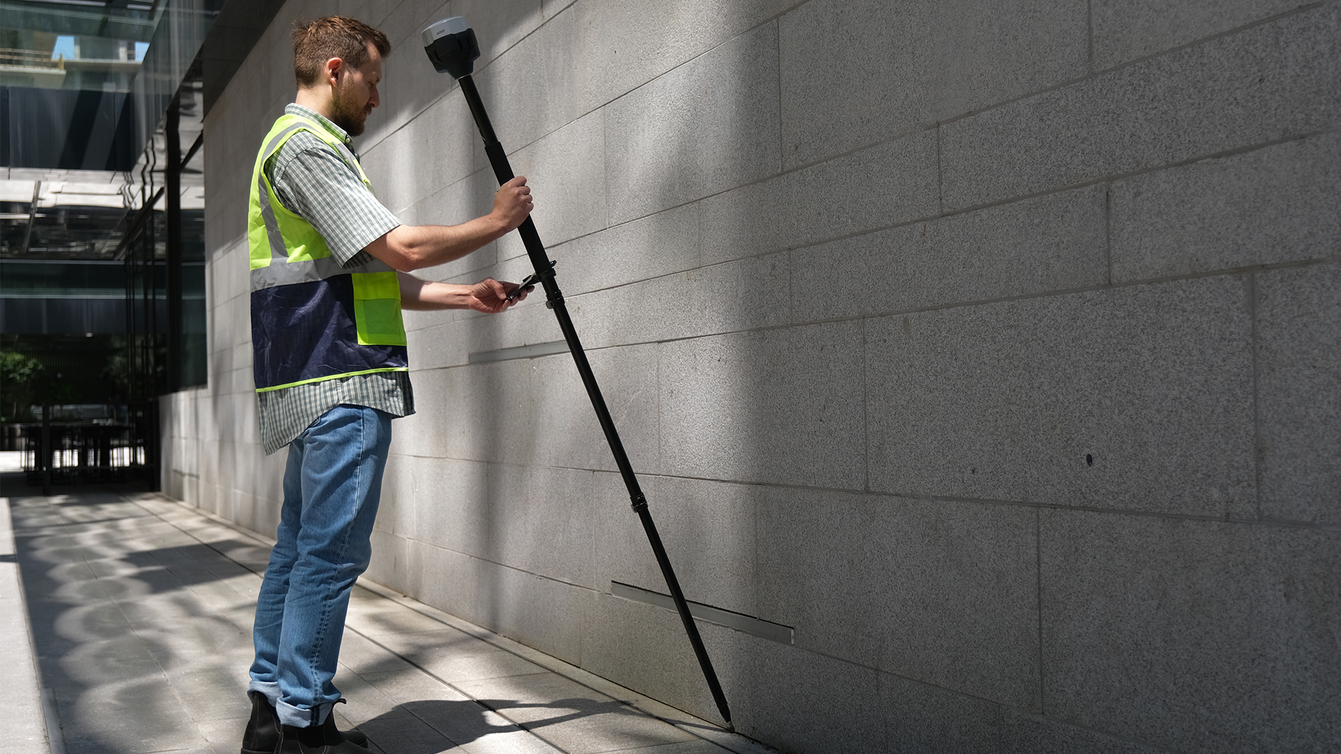
A more modern and often more time-saving method is direct georeferencing using GNSS data.
Here, the position of the scanner or sensor is determined during recording using satellite-based systems (e.g. Real-Time Kinematic = RTK).
Examples of GNSS-supported systems are:
- DJI M350 RTK (UAV with RTK module)
- XGRIDS LIXEL L2 Pro (mobile scanner with optional GNSS module)
The GNSS positions are linked to the scan data so that the point cloud is automatically located in the global coordinate system.
For drone or mobile scans, this enables fast, large-area capture with direct spatial classification.
Advantages:
- Fast workflow without manual calibration
- Ideal for large-scale outdoor photography
- Compatible with modern RTK systems
- GNSS support stabilises trajectories and improves the accuracy of SLAM or photogrammetric point clouds, especially for large-scale outdoor photography
Disadvantages:
- Dependent on GNSS signal quality (limitations in narrow streets or indoor spaces)
- Accuracy may be lower than with target-based methods
This method is ideal for topography, road surveying, construction site documentation and drone flights.
Georeferencing using feature points
If no targets or GNSS data are available, a point cloud can also be georeferenced retrospectively.
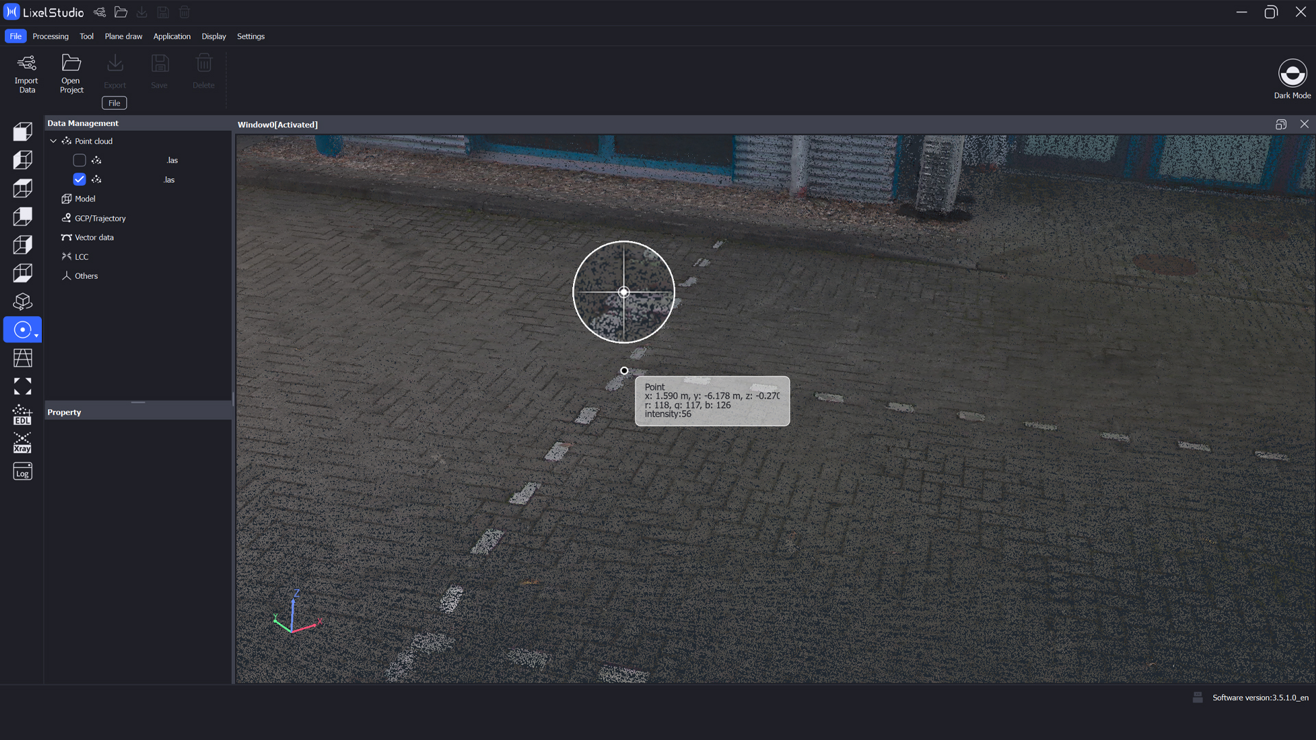
This involves selecting feature points in the point cloud (e.g. building corners, shafts or edges) whose coordinates are known from another data set or plan.
In the analysis software (e.g. CloudCompare, PointCab or FARO Scene), the point cloud is adjusted to the known coordinate system using these points.
Advantages:
- No additional measurements required on site.
- Can also be applied retrospectively to existing point clouds.
- Can be flexibly combined with CAD or GIS data.
Disadvantages:
- Dependent on the accuracy of the known points.
- Sources of error possible due to manual point assignment.
This method is often used to integrate SLAM scan data into a geodetic system.
Combination of multiple methods
In practice, a combination of multiple methods has often proven to be the most effective solution.
A typical example is the fusion of SLAM data with GNSS points:
A mobile scanner (e.g. XGRIDS Lixel K1 or Lixel L2 Pro) captures the environment using the SLAM method, while simultaneously recording GNSS positions at reference points.
In post-processing (e.g. with Lixel Studio), the GNSS data is used to stabilise the SLAM-based point cloud and bring it into the global coordinate system.
This combines the high relative accuracy of SLAM with the absolute positional accuracy of GNSS.
Avantages:
- High accuracy and stability over large areas
- Minimisation of drift errors in SLAM systems
- Ideal for projects with changing capturing conditions
Disadvantages:
- Somewhat more complex workflow in post-processing
- Requires experience in data matching and software use
This hybrid method is particularly suitable for large projects, indoor and outdoor combinations, or mobile scans where precision and efficiency are equally important.
TitleSoftware solution for georeferencing
Lixel Studio
Lixel Studio from XGRIDS enables the fusion of SLAM, IMU and GNSS data, ensuring an accurate, globally georeferenced point cloud. Lixel Studio is particularly useful in that it processes and transforms coordinates from ground control points and GNSS data so that the point cloud is located in the global coordinate system.
➡️ Ideal for mobile mapping and SLAM projects.
Scantra
Scantra specialises in the precise fusion of multiple SLAM runs and offers a powerful module for loop closures and accuracy verification.
➡️ Ideal for mobile mapping and urban surveying projects.
CloudCompare
CloudCompare is a free, open-source tool for manual georeferencing and transformation of point clouds (e.g. via ICP or Helmert).
➡️ Suitable for individual projects and post-processing.
FARO Scene
FARO Scene is the standard software for FARO scanners. It automatically detects targets and enables precise registration of multiple scans with the integration of GNSS or total station data.
➡️ Ideal for building surveys and industrial facilities.
TitleCommon mistakes & tips
Even with careful data capture, errors can occur during georeferencing. Knowing the common pitfalls helps to avoid discrepancies and maximise the accuracy of point clouds.
Common errors
- Incorrect coordinate system: Using different reference or elevation values leads to offset and misalignment.
- Swapped axes: X, Y or Z axes can be confused during import or transformation, causing the point cloud to tilt or shift.
- Inaccurate reference points: Incorrect GNSS or control points have a direct impact on georeferencing.
- Drift in SLAM data: Without correction by reference points, drift errors can occur, especially over long distances or in large indoor spaces.
- Insufficient visibility of targets: For target-based scans, all targets should be within the scanner's field of view, otherwise accuracy will decrease.
Practical tips
- Always check the coordinate system: Before capturing data, clarify which global system (e.g. UTM, Gauss-Krüger) is being used.
- Set control points: Additional points for validating georeferencing help to identify deviations.
- Combine SLAM data with GNSS: This reduces drift errors and increases absolute accuracy.
- Use software tools in a targeted manner: Automated target detection, loop checking or kinematic modules simplify the process.
- Do not neglect post-processing: A final check in software such as CloudCompare or Lixel Studio ensures that the point cloud is correctly aligned.
TitleConclusion: Precision through correct georeferencing
Georeferencing is crucial for correctly locating point clouds in space and combining them with other data sets. Whether using targets, GNSS, known points or hybrid solutions, the appropriate method depends on the project size and accuracy requirements.
Only a cleanly georeferenced point cloud enables precise analyses, accurate BIM models and efficient planning processes. This turns raw survey data into a reliable basis for surveying, design and documentation.